Revit BIM Modeling Services for Residential Buildings
Explore Revit BIM Modeling Services for a 22-Storey Residential Project, Including Architectural Plans, Elevations, Zoning, Energy, and BIM Documentation.
Revit BIM Modeling Services for a 22-Storey Residential Building with Detailed Architectural Documentation
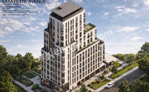
The uploaded project presents a detailed architectural and BIM documentation package for a 22-storey residential building identified as Lafayette Avenue, Louisiana, USA. The project presentation states an area of approximately 18,800 sq ft and identifies work related to construction documentation, energy and zoning analysis, quantity takeoffs and data extraction, BIM standards, and quality control. The presentation also identifies Revit 2024, Navisworks, and AutoCAD as software used for the project.
The drawing set provides more than a simple floor plan. It shows architectural floor documentation, a partial reflected ceiling plan, building elevations, north envelope and energy calculations, zoning deductions, thermal bridge calculations, schedules, tables, and other technical information. The final architectural visualization helps connect this technical documentation with the overall building form.
This project shows how Revit BIM Modeling Services can connect architectural design, documentation, building analysis, schedules, and visual communication in a coordinated digital workflow.
Detailed Architectural Understanding of the Lafayette Avenue Project
A 22-Storey Residential Building Presented Through BIM Documentation
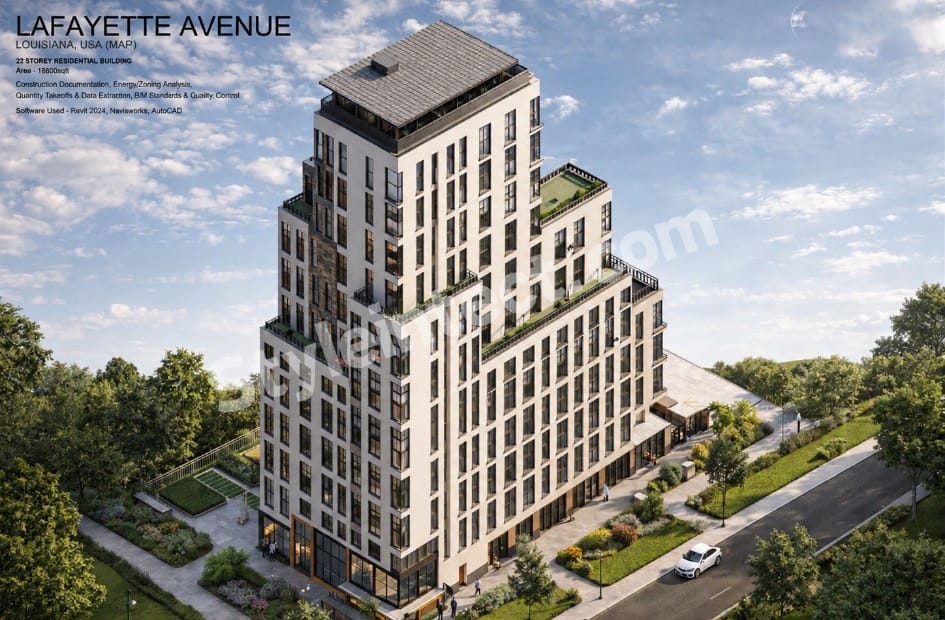
The project image clearly identifies the building as a 22-storey residential building. The architectural visualization shows a vertically developed building composed of several connected volumes with different heights.
The massing creates a stepped profile rather than a single uninterrupted rectangular block. Several upper-level setbacks and elevated portions are visible, giving the building a layered architectural character.
The technical elevations support this understanding by showing the building vertically across multiple levels. Horizontal level markers and detailed facade information are included around the elevation drawings.
Stepped Building Massing and Terraced Areas
The rendered view shows a central taller portion surrounded by lower building volumes. Some of the lower and intermediate roof levels appear to incorporate landscaped or green terrace areas.
The stepped arrangement is also reflected in the elevation drawings, where different building heights create a varied skyline. This type of massing can be clearly represented within a Revit architectural model because individual building elements and levels can be developed as connected but separately controlled components.
The visual presentation therefore complements the technical drawings by showing how the building’s overall massing is experienced in three dimensions.
Architectural Visualization and Technical Drawings Working Together
One of the strongest features of the uploaded set is the relationship between the technical drawings and the final architectural visualization.
The visualization provides an overall view of the building, surrounding pedestrian areas, road access, landscaping, terraces, windows, entrances, and exterior form. The drawing sheets provide the technical information needed to understand plans, elevations, zoning, energy-related calculations, and documentation.
Together, these outputs demonstrate how digital architectural design can support both visual communication and technical documentation.
Revit BIM Development Across Plans, Elevations and Documentation
Detailed Floor Plan Representation
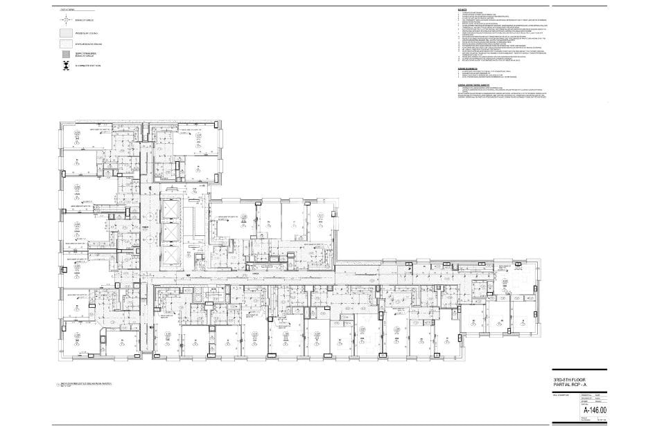
The uploaded floor plan sheet is titled “3RD-6TH FLOOR PARTIAL RCP – A”, indicating a partial reflected ceiling plan covering the third through sixth floors. The drawing contains numerous rooms, circulation areas, openings, dimensions, annotations, and architectural components.
The plan also includes multiple technical notes and drawing information around the building layout. Such information provides a structured basis for architectural documentation and can be represented within a BIM environment.
For a project of this scale, organized floor information is important because plans must remain connected to the broader building model and documentation process.
Elevation Documentation
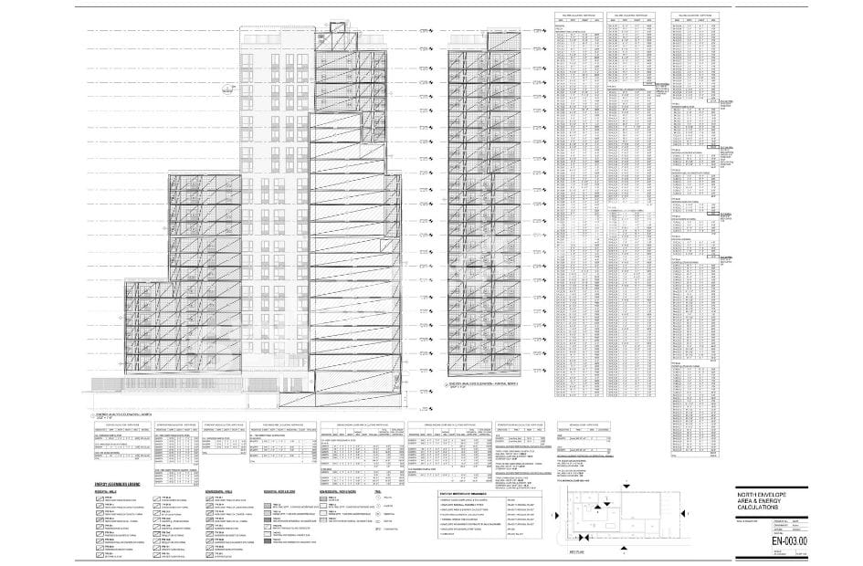
The uploaded elevation sheet presents several exterior elevations of the building. The drawings show the vertical organization of the building, repeated window arrangements, different building heights, roof levels, and facade openings.
The elevation information works alongside the rendered model. While the rendering communicates the architectural appearance from an aerial perspective, the elevation drawings communicate the building vertically and technically.
Revit Architecture Services can support this type of relationship by allowing architectural views to be generated from a coordinated building model.
Sections, Levels and Building Information
The drawings contain numerous level markers and technical references. The elevation documentation illustrates how the building changes vertically from lower levels to the taller residential portions.
A coordinated BIM model can organize these levels and associated architectural elements so that changes to the building design can be reflected across relevant views.
This is one of the practical advantages of Revit BIM Modeling: plans, elevations, sections, schedules, and other documentation can be developed from a connected digital building model rather than treated as completely separate drawings.
Building Envelope, Energy and Thermal Analysis Documentation
North Envelope Area and Energy Calculations
One uploaded sheet is explicitly titled “NORTH ENVELOPE AREA & ENERGY CALCULATIONS.” The sheet contains elevation information, calculation tables, legends, schedules, and supporting technical notes.
This indicates that the project documentation includes consideration of the building envelope and energy-related information. The envelope calculations appear to be connected with specific portions of the building elevation.
Such documentation can help organize information about the external areas of a building and provide a technical basis for building-performance-related evaluation.
Zoning Deductions and Area Information
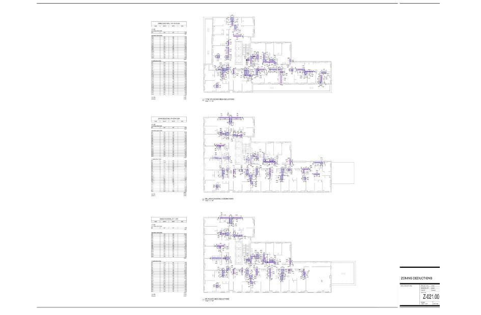
Another sheet is clearly titled “ZONING DEDUCTIONS.” It presents several floor-related diagrams accompanied by tables and calculated information.
The drawings visually distinguish selected areas within different floor layouts. This provides an example of how BIM documentation can be used to organize spatial and area-related information.
Area calculations and zoning documentation can be particularly useful on larger residential developments where building areas need to be clearly documented and reviewed.
Thermal Bridge Calculations
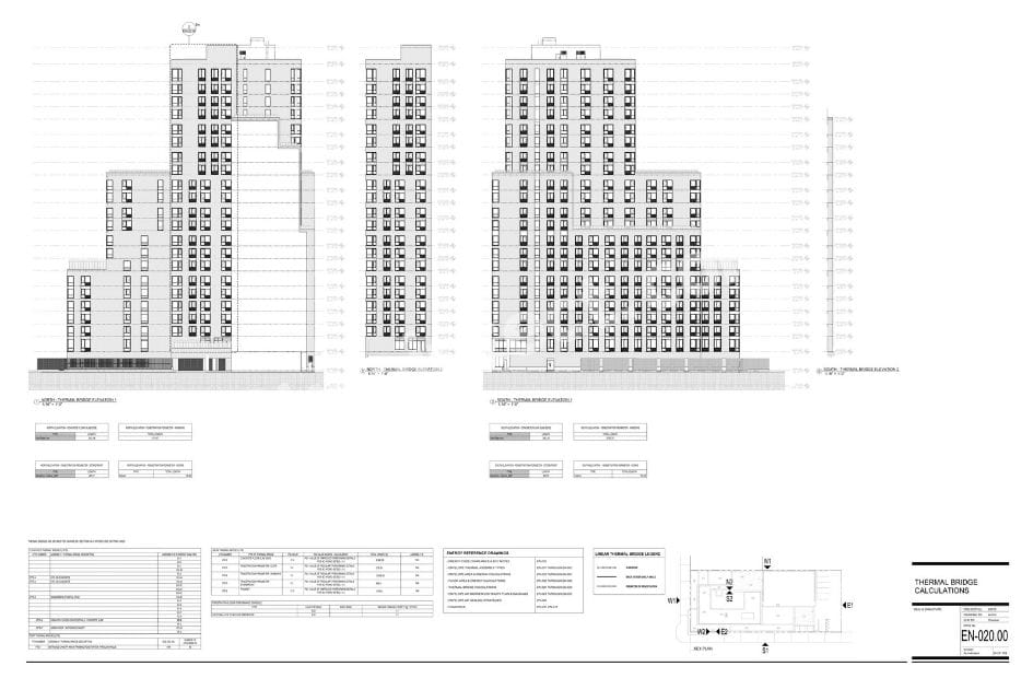
The fourth technical sheet is titled “THERMAL BRIDGE CALCULATIONS.” It contains building elevations, thermal-bridge-related tables, references, legends, and a key plan.
Thermal bridge analysis generally focuses on locations where heat flow through the building envelope can behave differently because of changes in geometry or construction. In this project, the uploaded documentation demonstrates that such information was included within the technical drawing package.
This strengthens the role of BIM documentation beyond simple architectural visualization by showing building-performance-related information.
Architectural Schedules, Data Extraction and Construction Documentation
Quantity Takeoffs and Data Extraction
The project presentation explicitly identifies “Quantity Takeoffs & Data Extraction” as part of the project scope.
A BIM model can contain structured information associated with architectural components. When that information is properly organized, schedules and quantities can support project documentation and review.
The uploaded drawings also contain several tables and schedules, showing that the project documentation includes substantial tabulated information alongside graphical drawings.
BIM Standards and Quality Control
The project presentation also identifies BIM Standards & Quality Control. This is important for a documentation package containing multiple plans, elevations, calculations, schedules, and technical sheets.
Quality control in BIM documentation involves maintaining consistency between views, information, naming, dimensions, schedules, and model outputs. A structured workflow helps reduce inconsistencies between different types of project documentation.
The uploaded sheets demonstrate the importance of organized information because the project combines architectural drawings with analytical tables and supporting technical data.
Construction Documentation Services
The uploaded set contains technical architectural drawings rather than only presentation images. Floor plans, elevations, schedules, calculations, zoning information, and envelope documentation all contribute to a broader construction documentation workflow.
Construction Documentation Services can therefore form an important part of a BIM project where design information needs to be communicated in a structured drawing package.
The images do not establish every construction detail or every project discipline, so the article does not assume additional structural or MEP documentation that is not visibly presented.
Software-Based BIM Workflow Shown in the Project
Revit 2024 for Architectural BIM Development
The project presentation explicitly identifies Revit 2024 as one of the software platforms used.
In the context of the uploaded project, Revit is relevant to the development of architectural building information, three-dimensional building representation, plans, elevations, and documentation.
The relationship between the architectural visualization and the technical drawings illustrates how a digital building model can support multiple forms of project output.
Navisworks in the Identified Project Workflow
The project presentation also identifies Navisworks.
The uploaded images do not provide enough evidence to claim that a specific clash was detected or resolved. However, Navisworks is explicitly listed as project software, so it can reasonably be discussed as part of the identified BIM software environment.
In a BIM workflow, coordination software can help teams review model information and coordinate digital project data. Specific coordination outcomes should always be based on documented project evidence rather than assumed.
AutoCAD and the Relationship with 2D Documentation
AutoCAD is also explicitly listed in the project presentation. Its presence indicates that the project workflow included a recognized 2D CAD environment alongside Revit and Navisworks.
The uploaded drawings contain extensive two-dimensional technical documentation. However, the images alone do not establish exactly which drawings were created in AutoCAD or which were produced from Revit.
Therefore, the appropriate conclusion is that AutoCAD formed part of the identified software environment, while the exact task allocation between applications is not assumed.
BIM Coordination, Digital Building Information and Project Workflow
Connecting Architectural Model Information
The project demonstrates a workflow where architectural information is represented through several connected documentation types. The rendered building provides the three-dimensional design view, while floor plans and elevations provide technical representations.
The zoning, energy, thermal bridge, and area-related sheets add another layer of information to the documentation package.
This is the broader value of Building Information Modeling Services: architectural information can be organized as a digital building model and then communicated through different views and data outputs.
From Architectural Design to Technical Documentation
The visible project can be understood as a documentation workflow involving architectural design, building modeling, drawing production, schedules, calculations, and presentation.
A simplified workflow relevant to the uploaded project is:
Architectural Design → Revit BIM Development → Plans and Elevations → Schedules and Data → Energy/Zoning Documentation → Technical Review → Project Presentation
The images do not prove that every possible BIM stage was completed, so this workflow should be understood as a representation of the visible project outputs rather than a claim about undocumented processes.
Why Choose StyleIntect for Revit BIM Modeling Services?
StyleIntect.com specializes in Revit BIM Modeling Services, BIM Modeling Services, Architectural BIM Services, Revit Architecture Services, 3D BIM Modeling, BIM Coordination, BIM Documentation, Architectural Design, Construction Documentation, Revit Modeling, BIM Project Development, Residential BIM Services, Commercial BIM Services, and Digital Architectural Design Solutions.
For projects similar to the uploaded Lafayette Avenue documentation, these capabilities are relevant to the connection between architectural modeling and detailed documentation. The focus can remain on organized digital building information, architectural drawings, model development, and project-specific documentation.
StyleIntect’s services can be aligned with different stages of architectural BIM work without making unsupported claims about project outcomes.
Architectural Building Visualization and Site Context
Exterior Form Shown in the 3D Presentation
The final uploaded visualization shows the residential building from an elevated perspective. The building has a light-colored exterior appearance, dark window framing, multiple vertical window groups, balconies or recessed areas, and several stepped roof or terrace levels.
The visualization also shows a strong vertical emphasis created by the taller central building volume.
Because the image is a rendered presentation, it provides a useful visual reference for understanding the massing represented by the technical elevation drawings.
Landscape and Pedestrian Areas
The rendered image visibly includes landscaped areas around the building. Trees, planted zones, pedestrian paths, lawns, and planted beds can be seen around the building perimeter.
A roadway and vehicles are also visible in the scene, providing context for the building’s relationship with the surrounding site.
These visual elements help communicate the project beyond the building envelope itself, although the uploaded technical sheets do not provide enough information to define a detailed landscape design scope.
Residential Building Character
The project presentation identifies the building as residential. The architectural rendering supports this classification through the repeated window openings, balconies or terraces, multiple residential-looking levels, and overall building organization.
The stepped form allows different portions of the building to have different heights. This creates a distinctive architectural silhouette while providing multiple exterior terraces and landscaped areas visible in the visualization.
Our BIM & Architectural Design Services for Similar Projects
Revit BIM Modeling and Architectural Revit Modeling
StyleIntect can provide Revit BIM Modeling Services and Architectural Revit Modeling for building projects where coordinated architectural information is required.
A Revit-based approach can organize building levels, architectural elements, plans, elevations, and model views within a structured digital environment. The exact model scope can be defined according to project requirements and available source information.
For residential developments, this approach can be particularly useful when the project contains multiple levels and repeated architectural components.
3D BIM Modeling and Construction Documentation
3D BIM Modeling Services can connect the visual representation of a building with its architectural documentation.
The uploaded project is a strong example of why this connection matters: the three-dimensional visualization communicates the building form, while the technical sheets communicate plans, elevations, schedules, calculations, and other project information.
StyleIntect’s architectural BIM capabilities can therefore be used to support digital building modeling and documentation workflows.
BIM Coordination and Digital Architectural Design
The project presentation identifies Navisworks as part of the software environment and also references BIM standards and quality control.
StyleIntect’s service range includes BIM Coordination and Digital Architectural Design Solutions. Where project information and model disciplines support it, coordination workflows can help organize digital project information for review.
Specific clash detection results or coordination outcomes should always be established from the actual project model and coordination reports rather than assumed from drawings alone.
Revit BIM Services for Residential Building Documentation
Supporting Large Architectural Drawing Sets
The uploaded project includes several different categories of drawings and calculations. Managing these outputs manually as isolated documents can make coordination more difficult as the project develops.
A structured BIM environment can help maintain relationships between architectural elements and their corresponding views.
For residential building projects, this can be valuable when multiple levels, elevations, schedules, and analytical drawings need to remain consistent.
Revit Floor Plans, Elevations and Schedules
The project demonstrates several documentation types that are closely associated with architectural BIM workflows. These include floor-related drawings, elevations, technical tables, schedules, and calculation sheets.
Revit Modeling Services can support the creation and organization of such project information, where the relevant content is developed within the model.
The goal is not simply to create a visually impressive 3D model. The model should also provide useful information for architectural documentation and project communication.
BIM Documentation for Different Project Stakeholders
Architects, engineers, contractors, developers, project managers, and other stakeholders may use different parts of a project documentation package.
A rendered model can help communicate design intent. Floor plans can communicate spatial organization. Elevations explain the external appearance. Schedules and calculations provide structured technical information.
This combination makes BIM Documentation Services relevant to projects where visual and technical information need to work together.
Applying the Project Approach Across BIM Markets
BIM Workflows in the United States
The uploaded project is explicitly identified as being in Louisiana, USA, making the United States the directly visible project context.
The drawing package demonstrates a combination of architectural documentation, energy-related information, zoning documentation, and technical calculations. Such project requirements show why organized digital documentation can be useful for complex building design workflows.
The article does not infer specific local code requirements because those requirements are not fully visible in the uploaded images.
BIM Services for International Architectural Projects
BIM workflows are also used for architectural and construction projects in markets such as the United Kingdom, Canada, Australia, India, UAE, Saudi Arabia, Qatar, and Europe.
The exact standards, regulations, documentation requirements, and project workflows can differ by location. For this reason, a BIM service should be adapted to the project requirements rather than assuming that one documentation approach applies everywhere.
Digital Building Information as a Project Communication Tool
The Lafayette Avenue project shows how one architectural development can be communicated through multiple information formats.
The rendered model explains the overall building character. The elevations explain vertical form. The floor documentation explains internal organization. The energy, zoning, and thermal sheets add analytical information.
This combination demonstrates the practical role of digital architectural information in communicating a complex building project.
Conclusion
The uploaded Lafayette Avenue project presents a detailed 22-storey residential building supported by architectural drawings, elevations, BIM documentation, zoning deductions, energy information, thermal bridge calculations, schedules, and a three-dimensional architectural visualization. The project presentation identifies Revit 2024, Navisworks, and AutoCAD within the workflow. For a project with this level of documentation, Revit BIM Modeling Services can provide a structured way to connect architectural design, digital building information, and technical documentation. StyleIntect.com offers relevant BIM, architectural modeling, coordination, and construction documentation services for similar project requirements.
FAQs
Q1. What is the primary BIM service relevant to this project?
The primary keyword selected for this project is Revit BIM Modeling Services, based on the visible Revit-based architectural documentation, 3D building presentation, plans, elevations, and technical BIM information.
Q2. What type of building is shown in the uploaded project?
The project presentation identifies it as a 22-storey residential building associated with Lafayette Avenue, Louisiana, USA.
Q3. Which software is identified in the project presentation?
The uploaded presentation explicitly identifies Revit 2024, Navisworks, and AutoCAD.
Q4. What technical information is visible in the drawing package?
The uploaded sheets include floor documentation, elevations, north envelope area and energy calculations, zoning deductions, thermal bridge calculations, schedules, tables, and other technical annotations.
Q5. Does the project show BIM coordination?
Navisworks is explicitly listed in the project presentation, indicating that it formed part of the identified software environment. However, the uploaded images do not provide sufficient evidence to claim specific clash-detection results or coordination outcomes.