
Modern 2D & 3D Floor Plan Layouts
Professional Architectural Services including 2D Floor Plan, 3D Front Elevation, Structural Drawings, Working Drawings, Plumbing & Electrical Drawings.

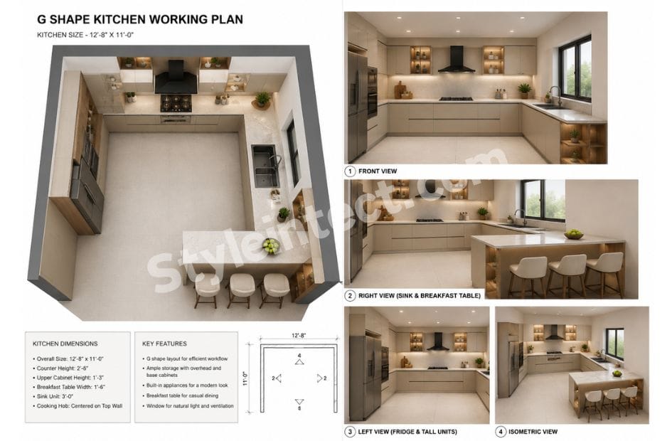
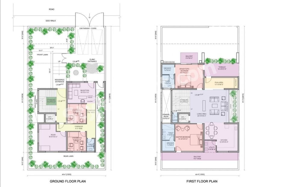
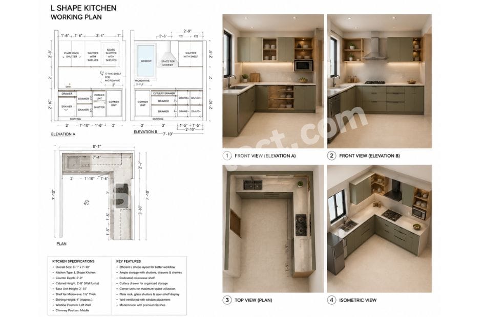
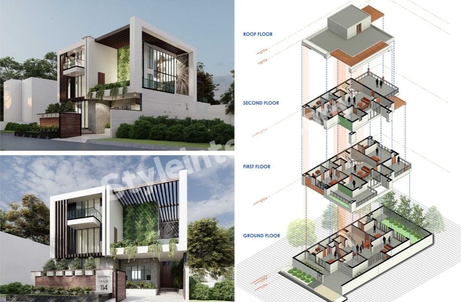

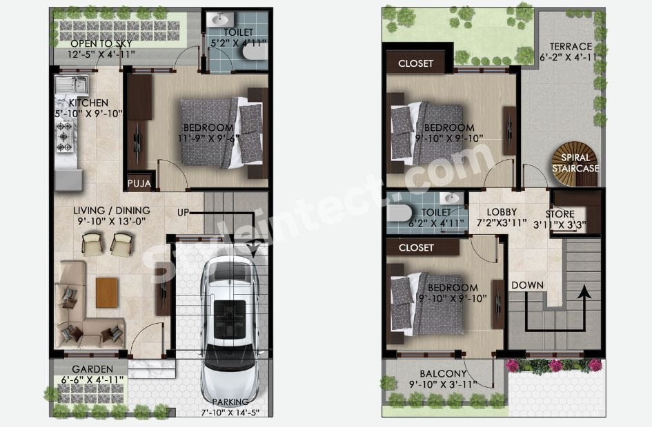


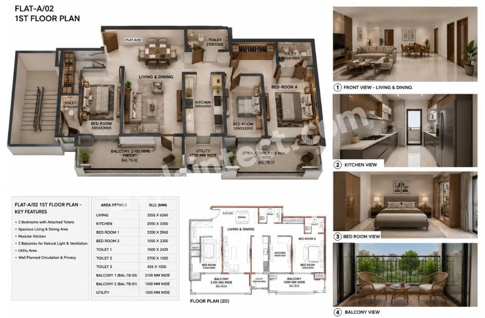
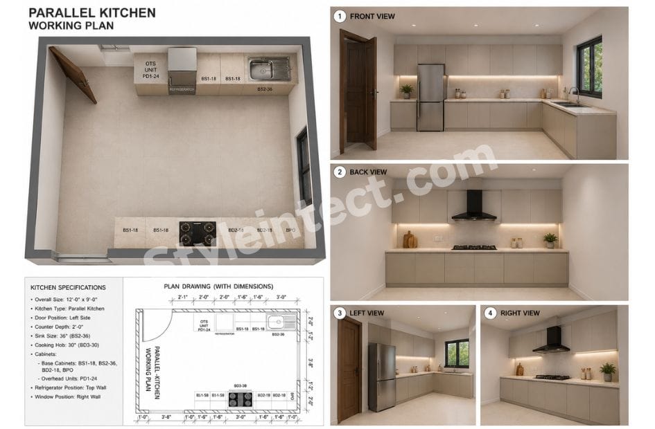
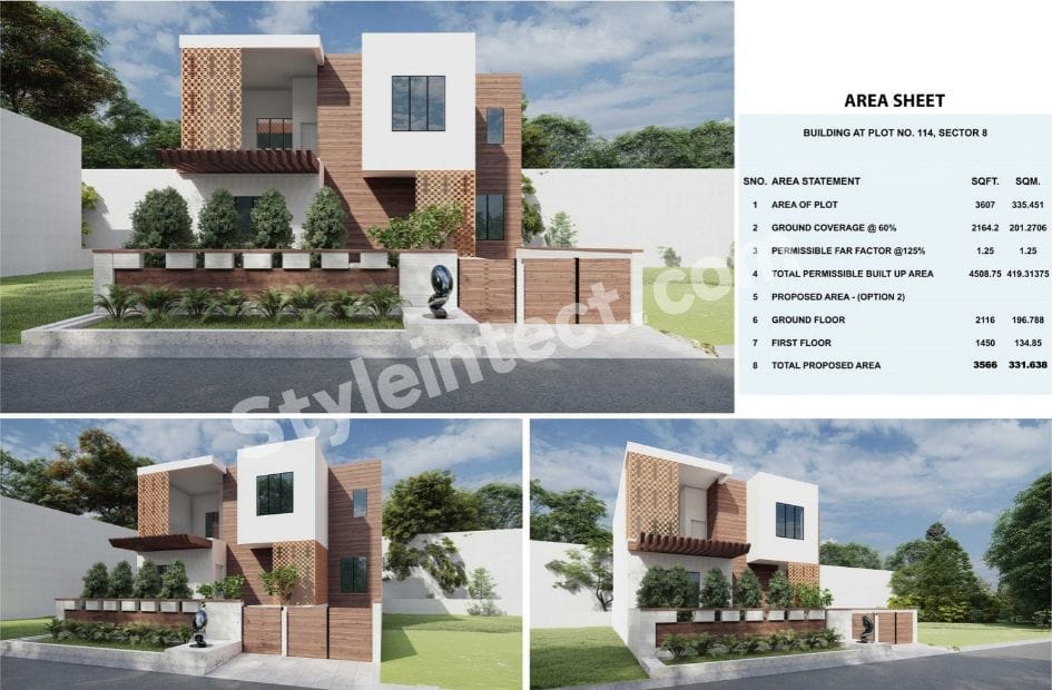


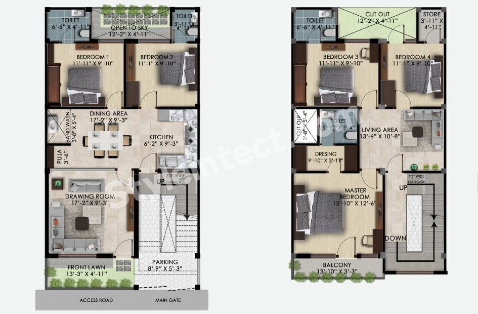
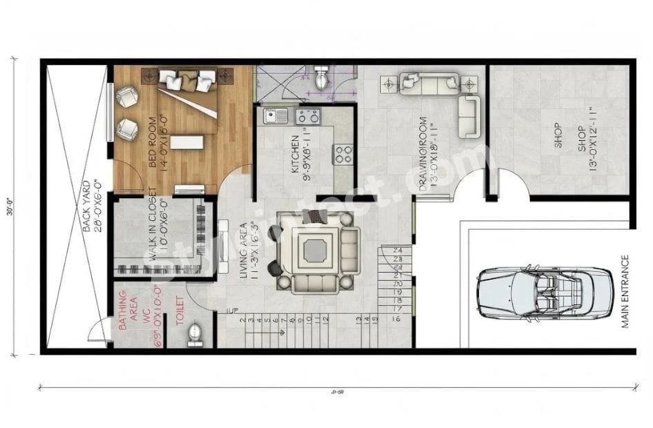
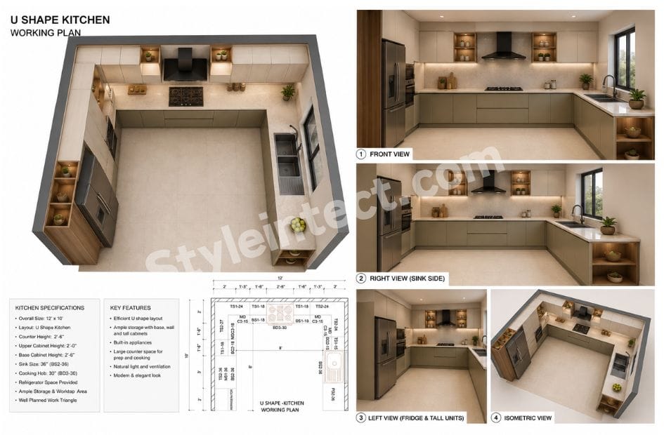
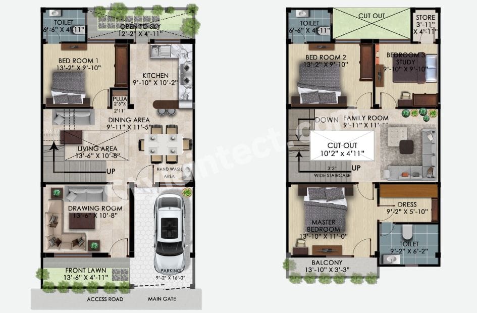
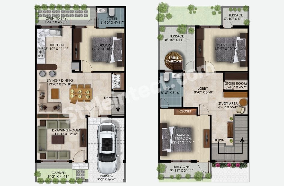
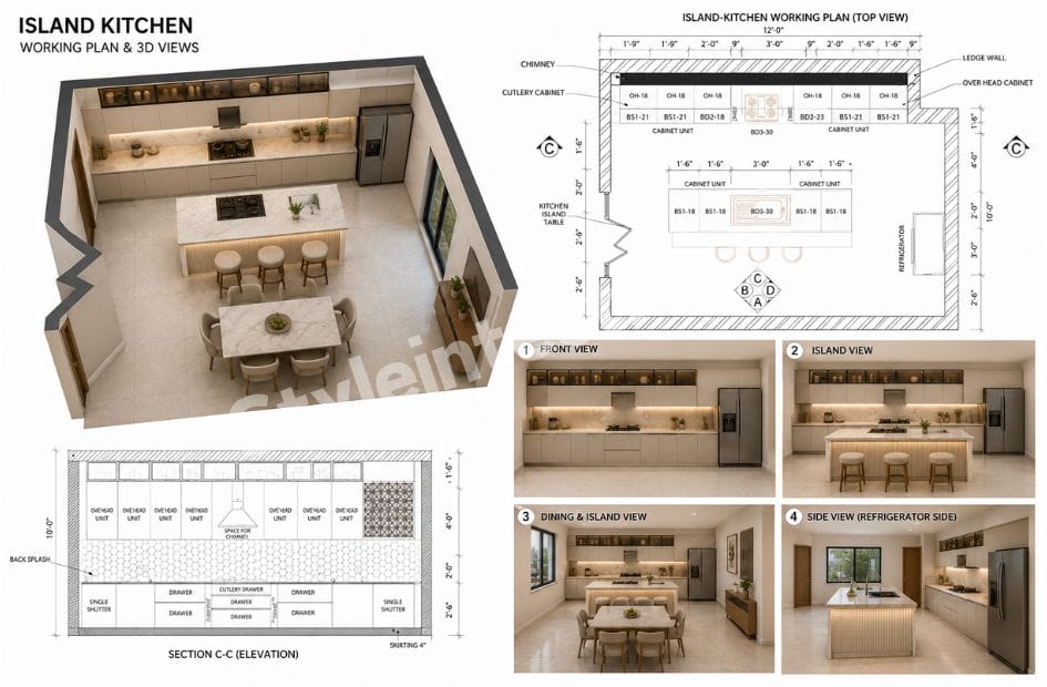


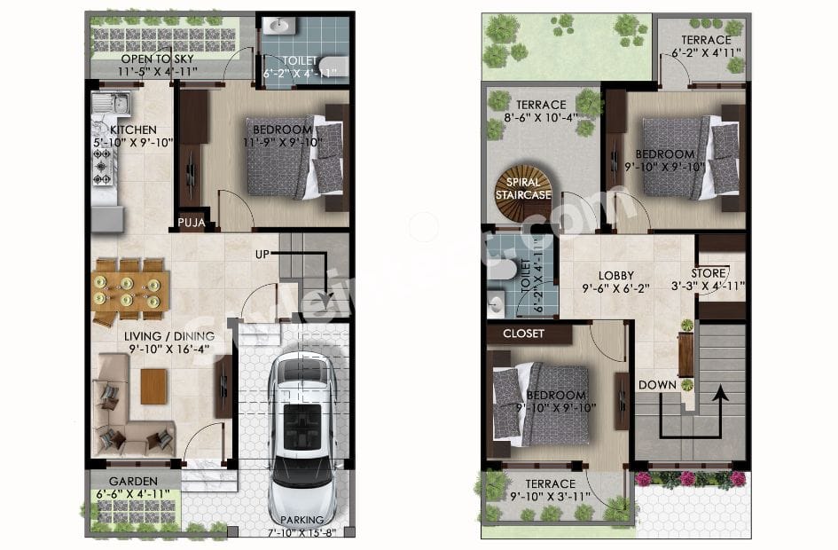
2D Floor Plans & 3D Front Elevation with Structural, Working, Plumbing & Electrical Drawings
Floor plan drawings serve as the visual language that coordinates architects and contractors throughout a construction project. Construction drawings provide information about design, materials, and specifications that prove vital for every stage from conceptualization to completion. In this piece, we’ll walk you through creating 2D floor plans that work and 3D front elevation designs. This includes structural drawing fundamentals, working drawing requirements, plumbing drawing layouts, and electrical drawings for complete project documentation.
What Are 2D Floor Plans and Why They Matter
A 2D floor plan is a scaled drawing without a viewpoint that shows the layout of rooms, walls, doors, windows, and other structural elements from a top-down view. Think of it as slicing through a building horizontally about five feet from the ground and looking down at the space from above. These flat representations use simple lines to depict walls, doors, and furniture. Construction drawings and technical documentation rely on them heavily.
I rely on 2D floor plans because they establish the foundation for designing and organizing spaces within any structure. These drawings aid architects, engineers, contractors, and builders with a precise illustration of both interior and exterior spaces. Stakeholders can assess the feasibility of design ideas when they study these plans. They make informed decisions about space allocation, room sizes, and circulation paths.
The value of floor plan drawings extends beyond simple visualization. They serve as a common language between various stakeholders involved in construction and reduce the chances of misinterpretation or errors. Professionals can identify potential design flaws and resolve them before construction begins with these drawings. This helps minimize costly and time-consuming modifications during the building process. 2D floor plans are instrumental in optimizing budgets since they provide accurate measurements and quantities of materials required for each building area.
Components of a 2D Floor Plan
A functional floor plan has several key project details. Walls appear as parallel lines, with thicker lines representing exterior or load-bearing walls and thinner lines showing interior partitions. Doors are drawn as breaks in walls with arcs that indicate swing direction, while windows appear as three parallel lines within wall breaks.
The compass mark shows property orientation, which matters for natural light considerations. Dimensions indicate actual physical sizes of spaces and elements, shown as thin lines with arrows or tick marks at each end. Room labels and numbers indicate intended use, whether it’s a bedroom, kitchen, or living area.
Floor plans also display furniture placement, electrical outlets, and plumbing fixtures using standardized symbols. These symbols form a visual language. Catalogs can have over 2,000 symbols to indicate furniture, equipment, and technical elements like electricity, heating, or plumbing. Fixed installations such as stairs, kitchen counters, and bathroom fixtures appear in their designated locations and help determine how space can be used around them.
Types of Floor Plans for Different Buildings
Different buildings require specific floor plan approaches. A house floor plan shows the layout of residential spaces like bedrooms, kitchens, and bathrooms. Homeowners and designers plan for comfort, privacy, and flow with these layouts. Restaurant floor plans map out dining areas, kitchen workflows, and customer circulation paths to ensure efficiency, safety, and a smooth guest experience.
Open floor plans remove walls to create flexible, shared spaces with better visibility, while closed floor plans divide areas for more privacy and room-specific use. Floor plans can follow various styles in residential architecture. Ranch-style plans work for one-story homes with bedrooms often separated from living spaces. Cape cod designs feature master bedrooms on the first floor with additional bedrooms on a half-story above. Two-story plans place most bedrooms on the second floor while living spaces remain on the first floor.
How to Create a Floor Plan
The process starts with measuring the space accurately. I measure room dimensions, door and window positions, and ceiling height using tape measures, laser tools, or LiDAR cameras for accuracy. I draft the layout next by sketching room boundaries and key features either on paper or digitally.
The right design tool comes next. Software options include AutoCAD, SketchUp, or Planner 5D based on experience level. These tools streamline the process with precision. I can import an existing floor plan or start from scratch and draw exterior walls by clicking to mark corners, then add interior partitions.
Details complete the layout. I place doors and windows from software catalogs, simply dragging, dropping, and adjusting placement. Then I add symbols for furniture, electrical layouts, or plumbing fixtures. Labels and dimensions improve clarity for design or construction teams.
Floor Plan Drawing Standards and Symbols
Floor plan symbols act as a standardized visual shorthand that everyone involved in construction understands. Walls use parallel lines with varying thickness to indicate type. Doors are shown as straight lines with curved arcs that depict swing paths. Windows appear as thin lines within wall breaks, often with three parallel lines where the center line represents glass.
Stairs are displayed as a series of rectangles or lines with arrows that indicate direction, labeled “UP” or “DN”. Electrical symbols include outlets (small circles with lines), switches (marked with “S”), and ceiling lights (circles with radiating lines). Plumbing symbols represent fixtures like sinks (ovals or rectangles with drains), showers (boxes or curved enclosures), and toilets (rounded bowl shapes).
Understanding 3D Front Elevation Drawings
“From a simple idea on paper to a façade that defines reality—every great design deserves the right vision, materials, and expertise.” — Alstone, Company.
A 3D elevation represents a three-dimensional rendering of a building’s exterior from different angles and displays height, depth, and width in photorealistic detail. These digital models present a realistic preview of how the finished structure will appear once construction concludes, unlike flat technical drawings. The front view remains the most common 3D elevation and typically serves as the main representation for clients and stakeholders.
What Is a 3D Front Elevation?
3D front elevation shows your building as viewed from the street and highlights the main entrance, balcony, gate, and façade design. This view creates the first impression of the structure and is most important for showcasing architectural identity. I can generate lifelike visualizations with specialized software that display exterior design, wall textures, doors, windows, balconies, roof shapes, and lighting effects. These renderings look closer to how the final building will appear after construction and incorporate colors, textures, shadows, and depth that technical blueprints cannot convey.
Key Elements in Front Elevation Design
Several factors shape how your 3D front elevation appears. Plot size and setback requirements influence design possibilities. Larger spaces allow more flexibility to experiment. The floor plan determines window frame sizes and placement, especially when you have front-facing spaces like living rooms and lounges. Geographic context matters a lot. Cold regions with heavy rainfall just need proper water drainage considerations and make flat roofs impractical. Earthquake-prone or flood-prone areas demand different standards for window sizes and material choices.
Front elevation designs must account for climate and location. Standard 3D front home elevation designs incorporate adequate sunlight exposure that conserves energy and regulates building temperature. Materials and textures are the visual foundations. Wall finishes, tiles, roofing patterns, window shapes, and paint colors appear in photorealistic detail and allow evaluation before construction begins. Lighting simulation is equally valuable. Architects can analyze how sunlight interacts with the building during different times of day.
Benefits of 3D Front Elevation Over 2D
The main advantage centers on realistic visualization. Clients no longer have to imagine how their building will look since they can actually see it in a photorealistic model. This addresses one of architecture’s biggest problems: communication. Many clients struggle to understand flat 2D plans, but 3D elevation design shows exactly how the project will appear and makes communication clear and straightforward.
Time and cost savings occur well before construction. Developing one side of a virtual home is faster and more affordable than traditional rendering and represents a fraction of the cost to modify a physical building’s structure, colors, or surroundings. Construction changes made after work begins become expensive, but 3D elevations prevent such issues. All design decisions can be finalized digitally first. I can experiment freely with multiple styles and instantly compare various color schemes, textures, and materials without physical samples.
Precision in measurements and proportions represents another benefit. Every detail from wall height to window placement can be viewed, edited, and approved in a realistic model. Early flaw detection becomes possible and allows me to spot proportion issues, unclear shapes, or unbalanced elements before construction begins.
Software Tools for Creating 3D Front Elevations
Professional architects rely on several advanced tools to create detailed 3D models. Autodesk Revit provides Building Information Modeling capabilities for precise architectural design. SketchUp offers user-friendly 3D modeling with extensive component libraries. 3ds Max with V-Ray delivers high-quality rendering with realistic materials and lighting. Lumion, Enscape, and Twinmotion specialize in live rendering and visualization. AutoCAD Architecture combines traditional drafting with 3D modeling features.
Structural Drawings: Building the Framework
Building authorities require licensed engineers to prepare, sign, and stamp structural drawings before any construction can proceed legally. These technical documents go beyond aesthetic considerations to define how a structure will stand physically, specifying load-bearing elements such as beams, columns, slabs, walls, and foundations with exact dimensions, materials, reinforcement layouts, and connections. Structural drawings function as the main communication tool between engineers and construction teams, ensuring the project remains stable under various loads while satisfying safety regulations.
What Are Structural Drawings
Structural drawings illustrate how a building is supported and held together through detailed plans that prioritize physical integrity over visual features. Engineers create these blueprints during the design phase to outline resource requirements for load-carrying elements, ensuring they meet safety, resistance, and durability standards. The documents include multiple components that work together: general arrangement drawings display grid lines, column placements, and beam configurations in plan view. Detailed drawings focus on reinforcement patterns in slabs and cross-sections of beams. Elevations with sectional views clarify vertical relationships and depth dimensions.
Schedules complement the graphical information by listing sizes, material grades, and identification numbers through column schedules, beam schedules, and reinforcement schedules. This organization improves readability and minimizes misinterpretation on site. Structural drawings serve as verification documents that demonstrate compliance with building codes, making them crucial to obtaining the permits needed from municipal authorities. They also provide construction instructions.
Column Layout and Foundation Plans
Foundation plans set the base reference for all structural work performed above ground level, illustrating dimensions and locations of footings, slabs, and basement walls. These plans specify foundation type, size, depth, and reinforcement details required to distribute building loads over a larger area. Column and beam layouts follow, showing the spatial relationship and positions of vertical supports with their connections to horizontal members.
Engineers set up grid systems to ensure proper arrangement of structural elements across different floors or sections. The grid creates reference lines that help position columns accurately, with each intersection point typically marking a column location. Foundation details include footing sizes calculated based on soil-bearing capacity. Column specifications indicate cross-sectional dimensions, material grades, and reinforcement requirements.
Beam and Slab Details
Reinforcement drawings detail bar spacing, lap lengths, bending shapes, and anchorage specifications for beams, columns, slabs, and foundations. Detailing standards require specifying concrete grade with a minimum 25/30 MPa strength and 20mm aggregate size for reinforced concrete slabs. Nominal cover to reinforcement follows standard requirements of 20mm for internal conditions and 40mm for external conditions.
Main reinforcement specifications include diameter, pitch of bars, location markers, and fixing dimensions to position bar runs accurately. Recommended minimum spacing for reinforcing bars stands at 75mm, with 100mm spacing for laps. Section and detail plans provide in-depth views of specific structural areas, showing internal structure with information about materials, dimensions, reinforcement placement, and layers within components.
Load-Bearing Components in Structural Design
Load-bearing systems comprise structural frameworks responsible for supporting and transferring loads from the building safely to the foundation and ground. Structural elements work together as a continuous chain where floor systems carry the weight of occupants and equipment. Beams and structural slabs transfer those loads to columns or load-bearing walls, and forces continue downward into the foundation before reaching supporting soil.
The load path represents the route structural forces follow as they move through the building. Walls act as vertical load-bearing components supporting floors and roof systems. Beams collect loads from slabs and transfer them to columns or structural walls. Columns carry loads downward through the structure, and foundations transfer building loads into soil. So as long as this load path remains continuous and is designed properly, the structure maintains stability and performs as intended without creating undesirable stress concentrations.
Working Drawings: The Complete Construction Guide
Contractors rely on working drawings to transform design concepts into physical structures. They receive dimensioned graphical information that guides every construction activity from site preparation through final finishes. These complete documents are part of the production information that designers prepare and pass to construction teams, including architectural drawings, structural drawings, civil engineering drawings, mechanical drawings, and electrical drawings. Working drawings create the instruction set needed to execute a project accurately, together with specifications and bills of quantities.
Types of Working Drawings
Traditional working drawings consist of two-dimensional orthogonal projections such as plans, sections, and elevations. Building information modeling has changed this approach by enabling three-dimensional representations called virtual construction models. Multiple models prepared by different project team members comprise these virtual construction models. Construction drawings describe overall design intent. Working drawings provide technical details needed for execution on site. Components include dimensions available in metric and imperial units, materials and specifications, structural reinforcements, electrical layouts, plumbing systems, HVAC installations, and fixing details for doors and windows.
Different professionals use these documents at various stages. Builders and contractors execute the construction. Electricians and plumbers install their respective systems, engineers supervise execution, and site managers coordinate all activities. Working drawings might be prepared for statutory approvals, construction planning, on-site instructions, component procurement, shop drawing preparation, or subcontractor appointments. Some packages require earlier production than others. Items with long manufacturing times such as switchgear, chiller units, lifts, or bespoke cladding systems need this early production.
Detail Drawings and Component Specifications
Detail drawings expand specific building parts at larger scales than standard floor plans or sections. They clarify connections that cannot be shown at smaller scales. The United States requires these drawings by law. Contractors must interpret intent independently without them, which causes errors, cost overruns, and potential architect liability if omissions create problems later. Three main types serve different purposes. Plan details are horizontal sections viewed from above, showing elements like thresholds or window jambs. Elevation details present flat views highlighting finishes and materials. Section details cut through buildings to show assembly connections, such as where walls meet slabs.
Core elements make detail drawings effective. Building material information specifies which materials are used and how they interact at connection points. Assembly and constructability information describes how separate components come together. Compliance information illustrates adherence to building codes and accessibility standards. Annotations specify performance requirements, material standards, and installation techniques that drawn lines alone cannot communicate. Connection information clarifies how building parts are joined and addresses the most vulnerable points where water, air, or structural forces are involved.
Assembly Drawings and Installation Guides
Assembly drawings represent items consisting of multiple components and show how parts fit together through orthogonal plans, sections, elevations, three-dimensional views, or exploded views demonstrating component relationships. These technical drawings provide step-by-step guides for putting complex items together, whether erecting building components or managing construction elements. They make cohesive communication between teams and stakeholders easier and act as standardized communication that allows processes to execute smoothly.
Installation drawings present information needed by trades to install parts of the works. They prove important for complex installations such as plant rooms, data centers, ventilation systems, and underfloor heating. General assembly drawings provide overviews showing how different components fit together. Sub-assembly drawings focus on specific sections detailing how smaller parts come together. Exploded view drawings show components separated slightly and provide clear views of fitting sequences.
As-Built Drawings and Documentation
As-built drawings reflect revised sets of drawings submitted by contractors upon project completion. They show all changes made in specifications and working drawings during construction. They document dimensions, geometry, and locations of all work elements completed under contract. Final as-built drawings include modifications, field changes, shop drawing changes, and design changes. Changes occur during construction because of site conditions on building projects, making as-built preparation standard practice.
These drawings serve four main purposes. They improve onboarding as subcontractors join projects and assist facilities teams with change records. They streamline permitting processes when government agencies request documentation and improve renovation processes by showing what was built. Architects or designers who designed projects create as-builts since they remain familiar with original specifications. Preparing as-builts requires attention, including reviewing original plans, taking field measurements, completing drawings, digitizing photos, and updating original design plans.
Plumbing Drawings for Water and Drainage Systems
“Our designs promote sustainable solutions for residential, commercial, and industrial buildings, maximizing water consumption and enhancing energy efficiency through cutting-edge technology.” — National MEP Engineers, Plumbing engineering service provider.
Plumbing drawings translate water supply and drainage requirements into practical installation instructions through clear schematics, standardized symbols, and precise specifications. These technical documents coordinate how fresh water reaches every fixture and how wastewater exits the building, preventing future leaks and maintenance issues while improving water efficiency and functionality.
Key Components in Plumbing Drawings
A complete plumbing drawing package has water supply layouts showing residential and commercial water line distribution, drainage system layouts detailing greywater and blackwater routes, isometric plumbing diagrams providing 3D views of pipe systems and fittings, and schematic diagrams with simplified flow representations. Toilet and kitchen plumbing details illustrate fixture connections and pipe layouts for wet areas. External plumbing layouts map connections between internal systems and municipal lines. Standardized symbols represent fixtures, valves, traps, and vents, with line types differentiating cold water, hot water, and waste paths. Color coding improves clarity: blue lines symbolize fresh water supply, red lines indicate hot water supply, black lines represent waste pipes, and yellow lines show venting pipes.
Water Supply and Distribution Plans
Fresh water enters buildings through main supply lines that connect to property boundaries and pass through water meters before branching via T-junctions to individual fixtures. Cold water lines use CPVC, UPVC, or PPR pipes chosen for durability and corrosion resistance. Hot water systems divert supply lines to geyser connections where heat-resistant piping carries heated water to bathrooms and kitchens. Vertical risers, wall chases, and concealed runs reduce pipe length, avoid sharp bends, and maintain pressure balance throughout distribution networks.
Drainage and Venting System Layout
Drainage relies on gravity flow with proper slopes to carry wastewater from buildings. The design separates flows into kitchen/utility gray water, bathroom gray water, and black water from toilets. Horizontal drainage piping requires uniform slopes of at least 1/4 inch per foot for 2-inch pipe sizes and smaller, and 1/8 inch per foot for 3-inch pipe sizes and larger. Bathroom waste flows into gully traps that feature water seals. These seals block foul odors and capture debris before routing gray water to main pipelines. Black water travels through separate, larger pipe systems into inspection chambers that collect multiple drainage branches leading toward main municipal sewers or septic tanks. Vent pipes supply fresh air to each fixture and protect trap seals against siphonage and back pressure while ensuring air circulation throughout drainage systems. Floor drains require water seals of at least 2 inches and removable strainers, with free open areas at least 2/3 of the cross-sectional area of nominal drain outlet size.
Fixture Locations and Pipe Sizing
Plumbing plans mark locations of all fixtures including toilets, sinks, and showers in floor plan views and label each fixture with clearances for accessibility. Pipe sizing depends on fixture unit load, flow demand, pressure, and pipe material. Each plumbing fixture has a defined water supply fixture unit (WSFU), with total demand determining pipe diameter to maintain adequate flow and pressure. Drainage materials include HDPE, PVC, ABS, uPVC, Cast Iron, Galvanized Steel, Lead, Copper, Brass, Stainless Steel, or extra-strength vitrified clay pipe with smooth, uniform bores. Changes in drainage piping direction use approved fittings at angles of 22.5°, 45°, 60°, or equivalent sweep.
Electrical Drawings: Power and Lighting Systems
Electrical systems need separate documentation drawn in a darker color than the background architectural elements to prevent confusion during installation. A complete electrical construction drawing set has plans for each structure, site plans showing utility services and substations, symbol and abbreviation lists, bills of materials, and one-line diagrams.
What Electrical Drawings Include
Electrical drawings provide precise layouts of wiring placement, power outlets, lighting, circuit breakers, panels, and equipment. Plans show outlet locations, switch placements, lighting fixtures, and circuit pathways. Graphic symbols follow standardized representations, with IEC 60617 serving as the current international standard, though symbols accepted locally should be used to clarify.
Outlet and Switch Placement Plans
The National Electrical Code requires that no wall point exceeds six feet from an outlet. Outlets must be within six feet of doorways and then every twelve feet along walls. Kitchen countertops need outlets spaced no more than four feet apart. Bathrooms need at least one GFCI-protected outlet within three feet of sinks on dedicated 20-amp circuits. Standard mounting heights range from 30-40 cm for general sockets and 105-110 cm for light switches.
Lighting Layout and Fixture Schedules
Lighting fixture schedules include fixture type or ID, quantity, mounting method, lamp specifications, wattage and voltage, control method, manufacturer reference, finish, and installation notes. These schedules ensure consistency across reflected ceiling plans and purchase orders.
Modular Home Solutions
Modular construction allows extensive interior customization without sacrificing design quality. We help you incorporate features like barn doors, shiplap, wainscot, tray ceilings, recessed lighting, built-in entertainment centers, and hardwood floors. Our flexible designs are tailored to your priorities, lifestyle, and budget, with expert guidance from concept to completion.
Electrical Panel and Circuit Design
Electrical panels distribute power through busbars to individual protective devices feeding lighting, socket circuits, motors, and equipment. Circuit protection has breakers rated according to circuit design, conductor capacity, and load characteristics. Three-phase systems need balanced load distribution across phases.
Wiring Routes and Load Calculations
Load calculations start by assuming 3 watts per square foot for lighting and general circuits, plus 1,500 watts for each 20-amp small appliance and laundry circuit. Total connected load combines these values with major appliance wattages. Demand load applies 100% to the first 10,000 watts and 40% to the remaining wattage. Dividing the demand load by 240 volts determines the amperage capacity required.
Conclusion
Complete construction documentation separates successful projects from pricey failures. Combine accurate 2D floor plans with realistic 3D elevations, proper engineering drawings that ensure structural integrity, detailed working drawings to execute the build, plumbing layouts to function well, and electrical plans to ensure safety. You create a complete roadmap that guides every stakeholder through the building process.
Proper documentation prevents expensive modifications during construction and ensures compliance with building codes. Each drawing type serves a purpose, yet they work together as an integrated system. Invest time in creating full documentation before breaking ground. Your attention to detail during the planning phase will save time, money, and headaches throughout construction and beyond.
FAQs
Q1. What exactly is a 2D floor plan and why is it important?
A 2D floor plan is a scaled drawing that shows the layout of a building from a top-down view, displaying rooms, walls, doors, windows, and other structural elements without perspective. It’s important because it serves as a common visual language between architects, engineers, contractors, and builders, helping them understand space allocation, room sizes, and circulation paths while identifying potential design flaws before construction begins.
Q2. How do you create an accurate floor plan?
Creating a floor plan starts with accurately measuring the space using tape measures, laser tools, or LiDAR cameras to capture room dimensions, door and window positions, and ceiling heights. Next, draft the layout by sketching room boundaries either on paper or using software like AutoCAD, SketchUp, or Planner 5D. Finally, add details such as doors, windows, furniture symbols, electrical outlets, plumbing fixtures, labels, and dimensions to complete the plan.
Q3. What are the main advantages of 3D front elevation over traditional 2D drawings?
3D front elevation provides realistic visualization that allows clients to see exactly how their building will look rather than imagining it from flat plans. It offers significant time and cost savings by enabling design experimentation with colors, textures, and materials digitally before construction. Additionally, it ensures precision in measurements and proportions while allowing early detection of design flaws, preventing expensive modifications during the building process.
Q4. What information do structural drawings contain?
Structural drawings specify load-bearing elements such as beams, columns, slabs, walls, and foundations with exact dimensions, materials, reinforcement layouts, and connections. They include foundation plans showing footing sizes and depths, column and beam layouts with grid systems for alignment, reinforcement details with bar spacing and bending shapes, and schedules listing sizes, material grades, and identification numbers for all structural components.
Q5. What are the essential components included in plumbing drawings?
Plumbing drawings include water supply layouts showing fresh water distribution to fixtures, drainage system layouts detailing wastewater routes, isometric diagrams providing 3D views of pipe systems, and schematic diagrams with flow representations. They use standardized symbols and color coding—blue for cold water, red for hot water, black for waste pipes, and yellow for venting—along with fixture locations, pipe sizing specifications, and connection details to municipal lines.