Revit BIM Modeling Services for Residential Buildings
Explore Ridgeway-VI, a 7-storey New York residential project using Revit BIM modeling, detailed floor plans, unit plans, roof design, and documentation.
Revit BIM Modeling Services for a 7-Storey Residential Building in New York
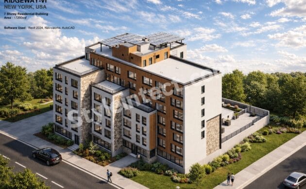
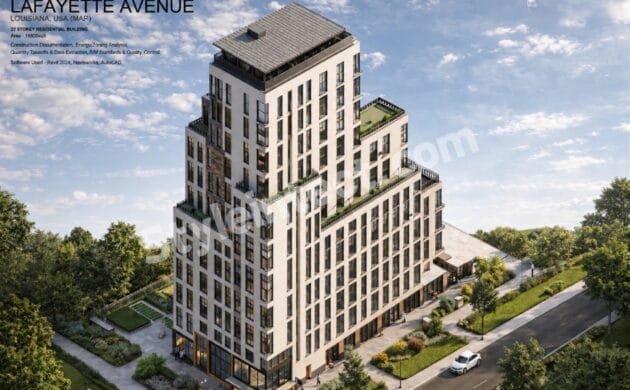
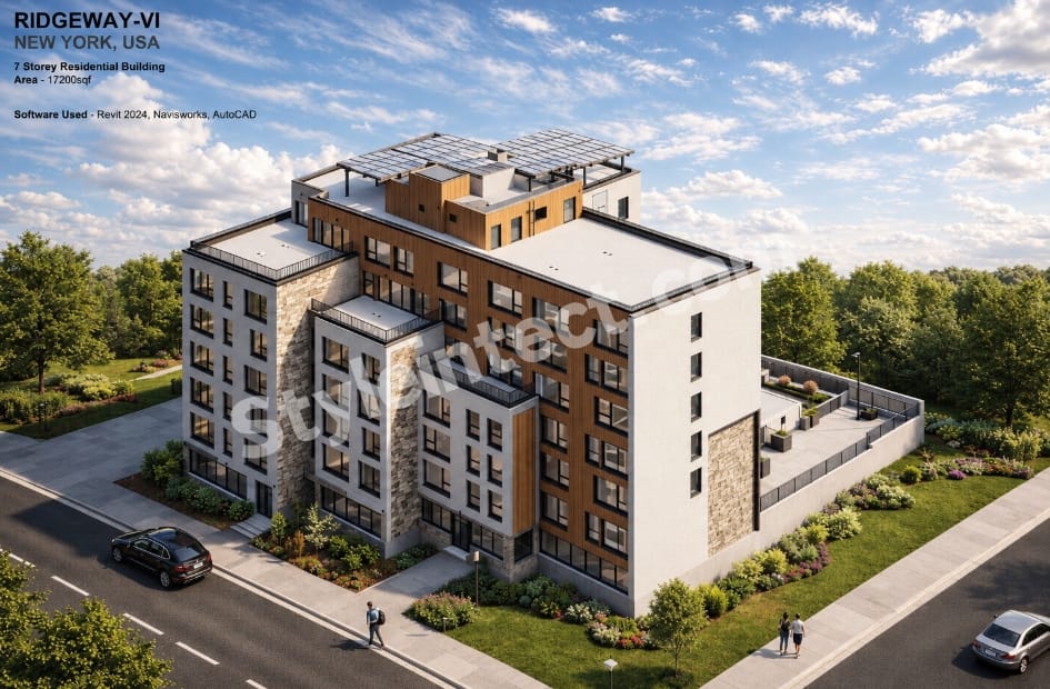
The uploaded project set presents Ridgeway-VI, identified in the project visualization as a 7-storey residential building in New York, USA, with an indicated area of 17,200 sq ft. The project presentation also identifies Revit 2024, Navisworks, and AutoCAD as software used for the project.
The uploaded documentation includes a detailed typical floor plan, roof plan, ground-floor slab edge and masonry plan, typical residential unit plans, and a 3D architectural visualization. Together, these drawings show how architectural design information can be organized across plans, technical drawings, unit layouts, and a digital building model.
The floor documentation contains dimensions, room labels, architectural symbols, drawing references, annotations, and technical notes. The unit plans further illustrate different residential layouts, while the roof and slab drawings provide additional information about the building’s physical organization. This makes the project a useful example of how Revit BIM Modeling Services can connect architectural modeling with structured construction documentation.
Understanding the Ridgeway-VI Residential BIM Project
A Project Presented Through Drawings and a 3D Model
The uploaded project is identified as Ridgeway-VI, New York, USA. The project visualization describes it as a 7-storey residential building with an indicated area of 17,200 sq ft. The visual presentation shows a contemporary multi-storey residential structure surrounded by landscaped outdoor areas and pedestrian and vehicular circulation.
The documentation gives a much more technical view of the same building. Instead of focusing only on appearance, the drawings show dimensions, room layouts, building edges, circulation, roof areas, unit configurations, and construction-related annotations.
This combination of a 3D presentation and technical documentation demonstrates the practical value of an organized digital architectural workflow.
Revit 2024, Navisworks, and AutoCAD in the Project
The project presentation explicitly lists Revit 2024, Navisworks, and AutoCAD under software used. Because these names are directly visible in the uploaded project presentation, they can be associated with the project without making assumptions about individual tasks.
Revit is particularly relevant to the visible architectural information because the project contains coordinated building plans, unit layouts, roof information, and a three-dimensional building representation.
AutoCAD is also identified in the project presentation, while Navisworks is listed as part of the software workflow. However, the uploaded sheets do not show a dedicated clash report or a Navisworks coordination screen. Therefore, clash detection should not be presented as a confirmed deliverable based only on these images.
A Residential Building with Multiple Documentation Levels
The drawing set includes several levels of architectural information. The typical floor drawing shows repeated residential planning across upper floors, while the roof plan focuses on the building’s uppermost organization.
The typical unit plans provide a closer look at individual residential configurations. These include living/dining areas, bedrooms, kitchens, bathrooms, circulation spaces, and utility-related information.
This layered documentation is important in Architectural BIM Services because different project stakeholders need different views of the same building information.
Revit-Based Development of the Architectural Building
Building Massing Visible in the 3D Presentation
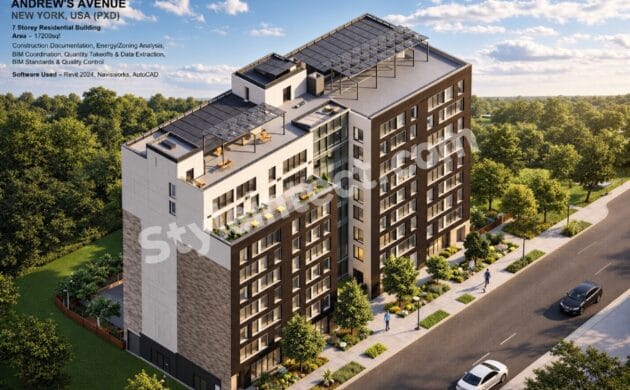
The 3D project image clearly shows the building’s overall massing. The residential structure consists of several connected volumes with different façade depths, roof levels, projecting portions, balconies or terrace-like areas, and large window openings.
The building has a contemporary architectural appearance, with contrasting light and darker façade zones visible in the visualization. The massing is easier to understand from the rendered view than from an individual two-dimensional drawing.
A Revit-based building model can represent this type of geometry as a connected digital environment, allowing architectural elements to be viewed from multiple directions.
Connecting Floor Plans With Three-Dimensional Design
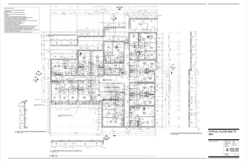
The uploaded typical floor plan provides a detailed two-dimensional representation of the residential building. It includes numerous room layouts, dimensions, wall lines, doors, fixtures, circulation areas, and architectural symbols.
The 3D visualization then presents the building as a complete object rather than as separate floor drawings. This relationship is central to Revit BIM Modeling because architectural information can be developed as part of a building model instead of being treated only as disconnected drawings.
The project therefore demonstrates the importance of maintaining a clear connection between design geometry and documentation.
Digital Architectural Design for Residential Projects
A digital building model can support residential design by organizing spaces, walls, openings, floor elements, roofs, and other architectural components within one project environment.
In the Ridgeway-VI documentation, the presence of multiple residential units makes this especially relevant. Similar layouts appear across the typical floor documentation, while the separate unit-plan sheet presents individual configurations at a larger scale.
This type of structured approach is useful for Residential BIM Services, particularly when a project contains repeated units and multiple documentation requirements.
Detailed Floor Planning and Residential Unit Organization
Typical Second and Third Floor Planning
One of the uploaded sheets is titled “TYPICAL FLOOR 2ND TO 3RD” and carries the drawing number A-103.00. The plan contains a substantial amount of architectural information, including grid references, dimensions, room labels, doors, windows, fixtures, circulation, and drawing callouts.
The drawing also contains areas identified as residential units and common or supporting spaces. The repeated planning information indicates that the sheet is intended to document a typical floor condition.
For Revit Architecture Services, such floor information can form an important part of the architectural documentation package.
Individual Unit Plans and Area Information
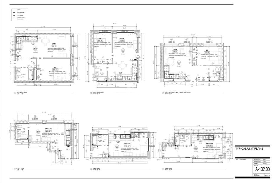
The sheet titled “TYPICAL UNIT PLANS” carries drawing number A-132.00. It presents several individual residential layouts at a larger scale.
Visible unit drawings contain labels such as BR and LR/DA, representing bedroom and living room/dining area spaces. The drawings also show bathrooms, kitchens, circulation, windows, doors, fixtures, and dimensions.
Several unit diagrams include visible area information and notes concerning required glazed areas. This is useful project information because it demonstrates that the documentation is not limited to simple room arrangements; it also incorporates measurable architectural information.
Room Relationships and Practical Space Planning
The unit plans show how different residential spaces are arranged in relation to one another. Living areas are positioned alongside kitchens and dining zones, while bedrooms and bathrooms occupy separate parts of the layouts.
The plans also illustrate different unit configurations rather than presenting a single repeated apartment arrangement. This creates a more detailed architectural documentation requirement.
A structured Revit BIM model can help organize these different layouts while keeping the architectural elements associated with their respective spaces and floors.
Roof Design and Upper-Level Architectural Information
Reading the Roof Plan
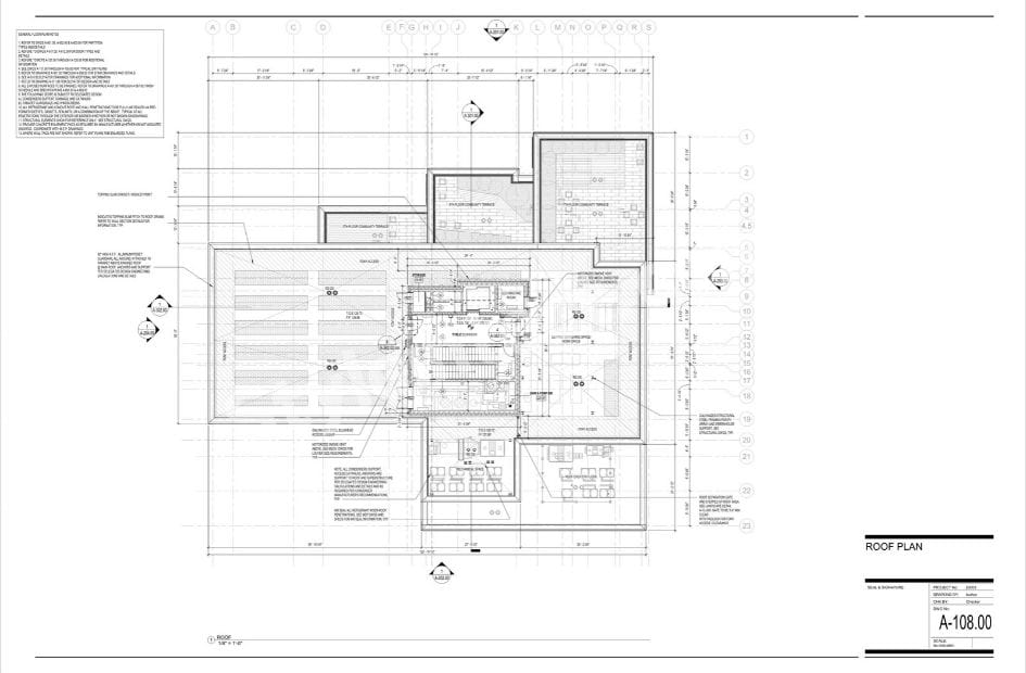
The second uploaded technical drawing is titled “ROOF PLAN” and carries drawing number A-108.00. The drawing shows the roof geometry, central circulation and service areas, multiple roof zones, terraces, and access-related information.
The roof outline is not simply a single rectangle. It contains several stepped and projecting portions that correspond with the building massing visible in the 3D presentation.
This type of geometry requires careful architectural documentation because roof edges and changes in level need to correspond with the overall building design.
Terraces and Roof-Level Spaces
The roof drawing visibly identifies several roof/community terrace areas. It also shows a central enclosed zone containing stairs and other spaces, along with additional roof-access areas.
The drawing contains notes and technical callouts around the roof perimeter. These annotations provide additional information about roof construction and access conditions.
From a BIM perspective, documenting these areas within a coordinated architectural model can make it easier to understand how the roof relates to the floors below.
Roof Geometry as Part of Revit Modeling
Roof geometry is an important component of Revit Architectural Modeling because the roof must correspond with walls, parapets, upper-level volumes, terraces, and other building elements.
The uploaded 3D image reinforces this relationship. The rendered building clearly shows multiple roof planes and elevated architectural volumes rather than one uniform roof surface.
The roof plan and 3D presentation therefore provide complementary information: one explains the technical layout, while the other communicates the overall spatial form.
Ground Floor Slab, Masonry and Construction Documentation
Ground Floor Slab Edge and Masonry Plan
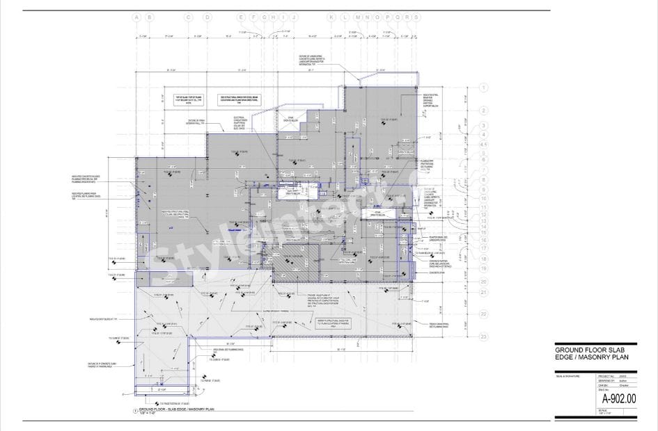
Another uploaded drawing is titled “GROUND FLOOR SLAB EDGE / MASONRY PLAN” with drawing number A-902.00. Unlike the typical residential floor plan, this drawing focuses on slab edges, masonry-related information, floor elevations, openings, and technical notes.
The plan contains shaded areas, outlined building edges, dimensions, elevation references, and notes concerning different construction conditions.
This demonstrates that the project documentation extends beyond room planning into more technical architectural information.
Construction-Oriented Annotations
The slab and masonry drawing contains numerous notes and callouts. Some visible annotations refer to slab conditions, structural steel locations, plumbing-related information, concrete areas, and other technical coordination points.
Because these details are directly visible, they demonstrate that the documentation addresses interfaces between architectural and other building requirements.
However, the images do not provide enough evidence to define a complete structural or MEP design scope. Therefore, those disciplines should not be described as fully modeled solely from these drawings.
From Architectural Design to Construction Documentation
Construction Documentation Services involve converting developed design information into drawings that can communicate how the building is organized and constructed.
The uploaded set demonstrates several documentation types: floor plans, roof plans, unit plans, and slab/masonry information. Each drawing serves a different purpose while referring to the same overall building.
This is one of the practical strengths of BIM-based documentation. A structured digital building model can provide a foundation for producing consistent architectural views while allowing project information to be presented at the required drawing scale.
BIM Documentation, Dimensions and Technical Information
Extensive Dimensions and Drawing References
The uploaded architectural drawings contain extensive dimensional information. Grid lines run across the plans, while horizontal and vertical dimensions establish the building’s overall layout and internal relationships.
The drawings also contain section and elevation callouts, detail references, room labels, door and window references, and other architectural symbols.
Such information makes the drawings useful not only as design presentations but also as technical documentation.
Architectural Schedules and Structured Information
The project drawings contain multiple annotations and references that organize architectural information. The unit-plan sheet also presents measurable room and glazing information.
While the uploaded images do not provide a dedicated standalone schedule sheet, the visible documentation shows the type of structured information that can accompany a BIM-based architectural project.
BIM Documentation Services can organize model information into plans, elevations, sections, schedules, and other project views when those deliverables are required.
BIM Quality Through Consistent Documentation
A key benefit of structured BIM documentation is consistency between different views. For example, a building element represented in a model can potentially appear in several associated drawings.
The Ridgeway-VI set illustrates why this matters. The building is represented through a typical floor plan, roof plan, slab/masonry plan, unit plans, and a 3D view.
When these views are developed from coordinated project information, they can provide different perspectives of the same architectural design.
3D BIM Visualization and Project Coordination
Architectural 3D Model Presentation
The uploaded Ridgeway-VI visualization provides a clear three-dimensional understanding of the project. The building is shown from an elevated exterior viewpoint, making the overall massing, façades, roof areas, windows, terraces, balconies, and site surroundings easy to understand.
The visualization also makes the relationship between the building and its surrounding landscape more apparent than the technical floor plans.
This is where 3D BIM Modeling Services can provide strong communication value for architectural projects.
Relationship Between Model and Technical Drawings
The 3D presentation and technical drawings complement one another. The render communicates form and appearance, while the drawings communicate dimensions, room organization, building edges, roof geometry, and technical information.
For architects and project stakeholders, viewing both forms of information can make a complex building easier to understand.
A digital architectural model can also support design communication by allowing the building to be reviewed from different viewpoints rather than relying only on conventional plan drawings.
Coordination Potential With Navisworks
The project graphic explicitly lists Navisworks among the software used. Navisworks is commonly associated with reviewing and coordinating building models, but the uploaded images do not show a specific clash-detection report or coordination result.
Therefore, the evidence supports identifying Navisworks as part of the stated project software environment, but not claiming a particular clash was detected or resolved.
This distinction is important for professional BIM Coordination Services, where actual coordination results should be supported by project evidence.
Why Choose StyleIntect for Revit BIM Modeling Services?
Project-Focused Revit BIM Modeling
StyleIntect.com specializes in Revit BIM Modeling Services, BIM Modeling Services, Architectural BIM Services, Revit Architecture Services, 3D BIM Modeling, BIM Documentation, Architectural Design, and Construction Documentation.
For a project such as Ridgeway-VI, the relevant BIM approach can focus on connecting architectural building geometry with floor plans, unit layouts, roof information, and technical documentation.
The uploaded project demonstrates the type of detailed architectural information that can benefit from a structured digital building workflow.
Our BIM & Architectural Design Services
StyleIntect’s relevant services include Revit BIM Modeling Services, Architectural BIM Services, Revit Architecture Services, 3D BIM Modeling, Revit Modeling, Architectural Design, Construction Documentation, Residential BIM Services, Commercial BIM Services, and Digital Architectural Design Solutions.
Depending on project requirements, these services can support architectural modeling and documentation for residential and commercial buildings.
For documentation-heavy projects, the goal is to maintain a clear relationship between the digital building representation and the drawings required for design communication and construction-related use.
BIM Applications for Residential Building Projects
Residential buildings with multiple floors and multiple unit types require organized architectural information. The Ridgeway-VI drawings demonstrate this through typical floor planning, individual unit plans, roof documentation, and slab/masonry information.
This type of project can benefit from a structured BIM project development approach because the building contains multiple related documentation layers.
StyleIntect can apply its BIM and architectural design capabilities to projects where clear digital modeling, drawing development, and documentation organization are important parts of the workflow.
Conclusion
The uploaded Ridgeway-VI project presents a detailed 7-storey residential building in New York, USA, supported by architectural plans, typical unit layouts, a roof plan, a ground-floor slab/masonry drawing, and a 3D project visualization. The project presentation identifies Revit 2024, Navisworks, and AutoCAD as software used. These materials demonstrate how Revit BIM Modeling Services can connect three-dimensional architectural representation with structured drawings and construction documentation. StyleIntect.com provides relevant BIM, Revit modeling, architectural design, and documentation services for similar digital building projects.
FAQs
Q1. What is the primary BIM service relevant to the Ridgeway-VI project?
The primary keyword selected for this project is Revit BIM Modeling Services, based on the visible Revit-based project presentation, detailed architectural drawings, floor plans, roof plan, unit plans, and 3D building representation.
Q2. What architectural drawings are visible in the uploaded project?
The uploaded documentation includes a typical second-to-third-floor plan, roof plan, ground-floor slab edge/masonry plan, and typical residential unit plans. A separate 3D architectural visualization presents the overall building.
Q3. Which software is identified in the Ridgeway-VI project?
The project visualization explicitly identifies Revit 2024, Navisworks, and AutoCAD as the software used. The uploaded images do not independently establish which specific task was completed in each software package.
Q4. Does the project show BIM clash detection?
The project presentation lists Navisworks, but the uploaded drawings do not show a clash-detection report or specific clash results. Therefore, clash detection should not be treated as a confirmed deliverable based only on these images.
Q5. How can Revit BIM Modeling support similar residential projects?
Revit BIM can provide a structured digital representation of architectural elements and support the development of coordinated project views such as floor plans, elevations, sections, schedules, and 3D documentation, depending on the project’s scope.