Revit BIM Modeling Services | St. Elizabeth's Manor Project
Explore St. Elizabeth’s Manor through Revit BIM modeling, architectural plans, elevations, sections, 3D design, and construction documentation.
Revit BIM Modeling Services for St. Elizabeth's Manor Residential Renovation
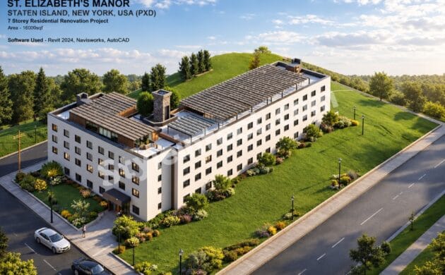
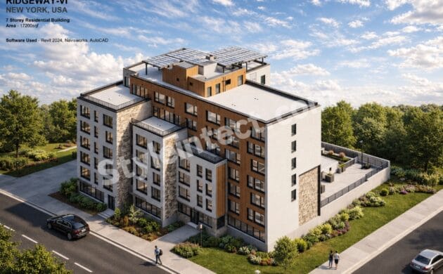
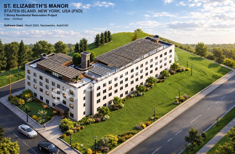
The uploaded project documentation presents St. Elizabeth’s Manor, Staten Island, New York, USA, identified in the project presentation as a 7-storey residential renovation project with an indicated area of approximately 160,000 sq ft. The presentation also identifies Revit 2024, Navisworks, and AutoCAD among the software used.
The drawings provide a detailed view of the architectural documentation, including a proposed first-floor plan, demo plan, proposed elevations, and multiple building sections. The project presentation also includes a 3D architectural view that helps communicate the overall building form, roof arrangement, site surroundings, landscaping, entrances, and exterior appearance.
The uploaded material shows how Revit BIM Modeling Services connect architectural design information with coordinated drawings and three-dimensional project communication.
Revit BIM Modeling for a Detailed Residential Renovation
Understanding the Visible Revit-Based Project
The project sheets show a coordinated set of architectural drawings rather than a single isolated drawing. The documentation includes plans, elevations, and sections that describe the building from different viewpoints.
The project presentation identifies the development as St. Elizabeth’s Manor and describes it as a seven-storey residential renovation. This gives the documentation a clear architectural context, while the drawings provide the technical information needed to understand the proposed building configuration.
The visible drawing set also includes sheet references such as A-101.00, A-200.00, and A-300.00, corresponding to the plan, elevation, and section documentation shown in the uploaded sheets.
Three-Dimensional Architectural Communication
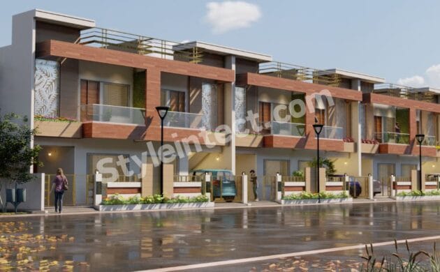
The 3D project image provides a visual representation of the building massing and exterior arrangement. It shows a long residential building with multiple levels, repeated window openings, rooftop forms, landscaped surroundings, pedestrian paths, road access, and defined entrance areas.
This type of three-dimensional representation makes it easier to understand the relationship between the building’s overall form and its surrounding site. It also complements technical drawings by presenting the project in a more visually accessible format.
For architectural teams, 3D BIM Modeling Services can provide a structured way to represent building elements while supporting communication between design documentation and visual project presentations.
Connecting Plans, Elevations and Sections
The uploaded sheets demonstrate the importance of viewing a building through multiple drawing types. The proposed plan provides information about the internal arrangement, while the elevations show the exterior composition and the sections explain the building vertically.
A coordinated BIM approach can help maintain consistency between these views. When architectural information is developed within a structured Revit environment, changes to modeled elements can be reflected across related documentation depending on how the project is configured.
Architectural Floor Plans and Building Organization
Visible Proposed First-Floor Plan
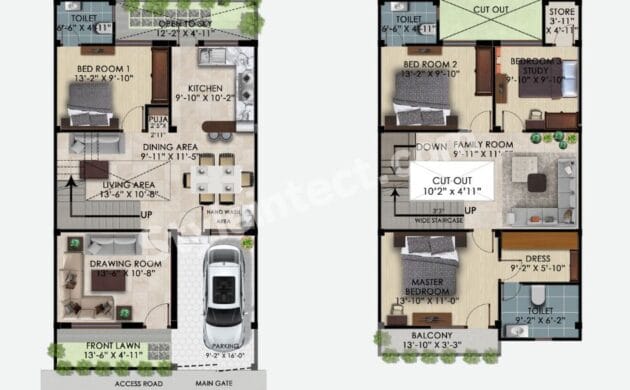
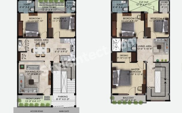
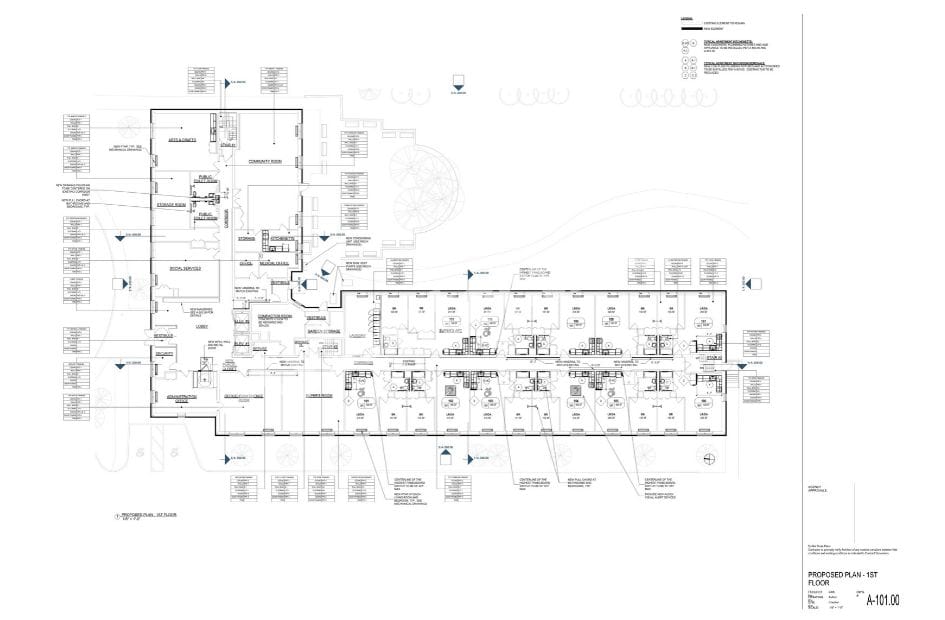
One of the uploaded drawings is clearly titled “PROPOSED PLAN – 1ST FLOOR”. The plan shows a combination of larger shared spaces, circulation areas, service spaces, and a long sequence of smaller rooms along the main building block.
Visible labels include spaces such as a community room, lobby, vestibule, conference-related spaces, storage/service areas, and multiple room or residential-unit layouts. Because the drawing contains many technical annotations, the plan provides considerably more information than a simple conceptual floor layout.
This makes architectural Revit modeling useful for organizing spaces, walls, openings, circulation routes, and other visible building components within a coordinated digital environment.
Room and Circulation Relationships
The first-floor drawing shows a central circulation arrangement connecting different areas of the building. Multiple rooms are organized along the elongated portion of the plan, while larger spaces are positioned toward the other side.
The visible corridors, entrances, vestibules, stairs, and service areas demonstrate why spatial coordination is important in a large architectural project. A structured BIM model can represent these relationships more clearly than disconnected two-dimensional lines.
Proposed and Demonstration Documentation
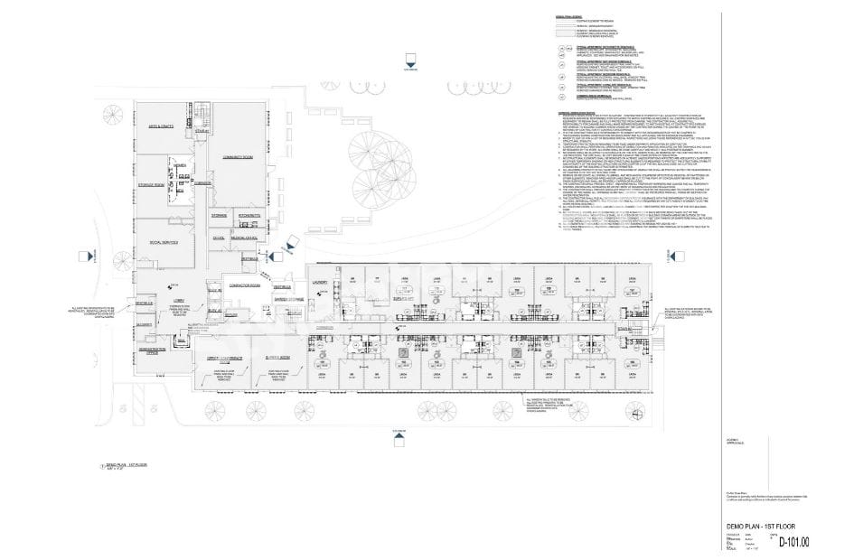
Another uploaded sheet is titled “DEMO PLAN – 1ST FLOOR.” Its presence alongside the proposed plan indicates that the documentation distinguishes between existing or demolition-related information and proposed conditions.
This is particularly relevant to renovation work. Architectural BIM documentation can help separate existing conditions from proposed changes when the project requires modifications to an existing building.
The combination of demolition documentation and proposed design information provides a clearer basis for understanding the renovation process.
Proposed Elevations and Exterior Building Design
Multiple Building Elevations
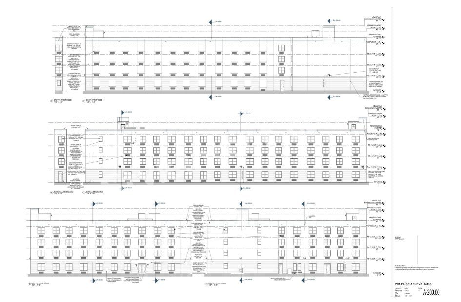
The elevation sheet is identified as “PROPOSED ELEVATIONS” and presents multiple sides of the building. The drawings show repeated window arrangements across several levels and different exterior conditions along the building’s length.
The elevation documentation also includes architectural reference markers, level information, notes, and other annotations. These elements help connect the exterior appearance with the dimensional and vertical organization of the building.
Repeated Window and Facade Organization
The proposed elevations visibly show a regular pattern of windows distributed across the building facade. Different portions of the building include variations in openings and facade composition.
The 3D presentation reinforces this visual organization. The rendered view shows repeated rectangular windows across the long exterior walls, creating a consistent architectural rhythm.
From a BIM perspective, repeated architectural elements can be represented as modeled components, making the building easier to coordinate and document.
Roof and Upper-Level Composition
The 3D presentation shows several distinct roof areas across the building rather than a single uninterrupted roof plane. The roofscape includes different levels, rooftop structures, and a prominent chimney-like vertical element.
The proposed elevations and building sections provide additional information about these upper portions of the building. Together, these drawings create a more complete understanding of the project’s vertical and exterior composition.
Building Sections and Vertical Documentation
What the Uploaded Sections Show
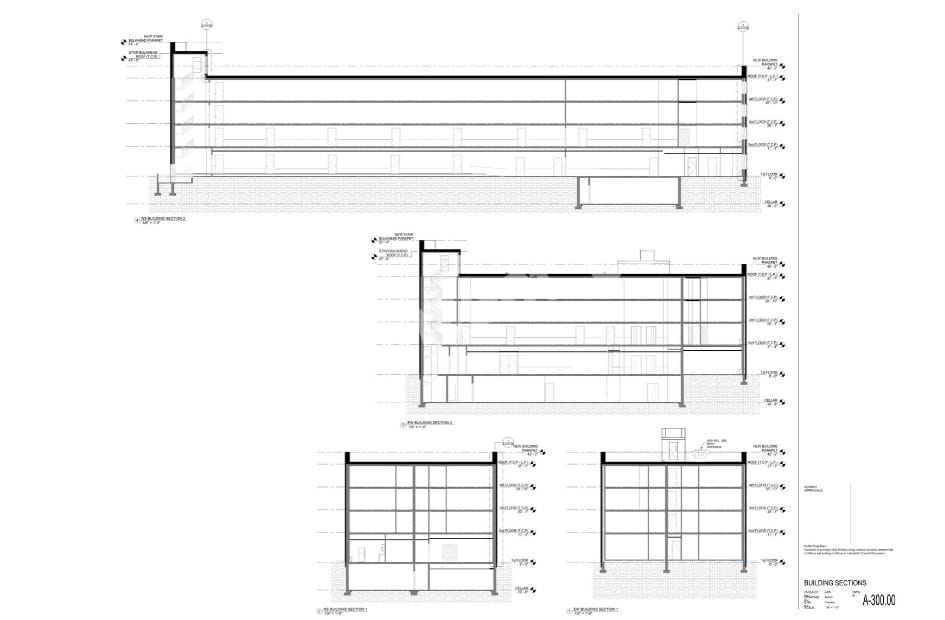
The first uploaded drawing is titled “BUILDING SECTIONS” and contains multiple sectional views. The sections illustrate the building vertically, showing floor levels, roof lines, wall profiles, openings, and relationships between different portions of the structure.
Section drawings are particularly valuable because they communicate information that cannot be fully understood from a floor plan alone.
Floor-to-Floor Relationships
The sections contain multiple horizontal level references associated with different floors. The visible documentation indicates several stacked building levels, consistent with the project presentation identifying the building as seven storeys.
The sections also show variations in the building profile. One section illustrates a long building volume, while other sections show narrower portions and different roof configurations.
This information can be represented through Revit Architectural Modeling, where levels, walls, floors, roofs, and other architectural components can be organized within a three-dimensional project environment.
Section-Based Construction Documentation
Building sections are an important part of architectural construction documentation because they explain vertical conditions and relationships between building components.
When plans, elevations, and sections are developed from coordinated architectural information, they can provide a more consistent documentation package. The uploaded project demonstrates the value of presenting all three drawing types together.
For a renovation project of this scale, section documentation also helps communicate how different parts of the building relate vertically without relying solely on the 3D presentation.
BIM Documentation, Schedules and Technical Information
Architectural Documentation Beyond the Model
The uploaded drawings contain numerous technical annotations, level markers, callouts, notes, dimensions, and drawing references. This demonstrates that the project documentation extends beyond visual modeling.
A BIM project can serve as a foundation for producing architectural documentation in an organized format. Depending on project requirements, this may include plans, elevations, sections, schedules, details, and other construction-related drawings.
The visible sheets demonstrate how technical documentation and architectural visualization can work together.
Drawing References and Sheet Organization
The project sheets visibly use architectural sheet numbering and drawing titles. For example, the plan is identified as A-101.00, the proposed elevations as A-200.00, and the building sections as A-300.00.
Organized sheet references make it easier for project stakeholders to understand which drawing contains specific information. This is an important part of professional BIM Documentation Services.
A structured documentation system can also help teams navigate large drawing sets more efficiently.
Area and Project Information
The project presentation explicitly states an area of approximately 160,000 sq ft and identifies the project as a 7-storey residential renovation project.
These details are treated here only as project information visible in the uploaded presentation. The drawings contain additional technical annotations and calculations, but this article does not assign values that cannot be clearly read from the supplied images.
This evidence-based approach is important when creating BIM documentation content because project information should come from verified drawings or project data rather than assumptions.
BIM Software Workflow: Revit, Navisworks and AutoCAD
Revit 2024 in the Project Presentation
The project presentation explicitly lists Revit 2024 under “Software Used.” Revit is commonly used for architectural BIM modeling, where building elements can be represented within a three-dimensional digital building environment.
For a project containing plans, elevations, sections, and architectural documentation, Revit can provide a connected environment for developing and documenting building information.
The uploaded drawings themselves show the type of architectural documentation that can be associated with a Revit-based workflow.
Navisworks and BIM Coordination
Navisworks is also explicitly listed in the project presentation. In BIM workflows, Navisworks can be used for reviewing and coordinating models from different disciplines and for project coordination activities.
However, the uploaded images do not visibly demonstrate a specific clash detection result or a particular coordination test. Therefore, it would not be accurate to claim that a specific clash was detected in this project based only on the supplied images.
The appropriate conclusion is that Navisworks is identified as part of the project’s software environment, while the exact coordination tasks performed are not fully demonstrated in the supplied sheets.
AutoCAD and Architectural Documentation
AutoCAD is also listed in the project presentation. AutoCAD is widely used for two-dimensional drafting and architectural documentation.
The uploaded drawings contain detailed 2D architectural information, including plans, elevations, sections, annotations, and drawing references. The images alone do not establish which individual drawing was created in AutoCAD versus Revit, so specific software-to-drawing assignments should not be assumed.
This distinction keeps the project analysis connected to the actual evidence visible in the uploaded material.
BIM Coordination and Digital Architectural Development
Coordinating Multiple Drawing Views
A major strength of BIM-based architectural development is the ability to organize multiple views of the same building. The uploaded project includes floor plans, elevations, sections, and a three-dimensional presentation.
These views describe different aspects of the same architectural proposal. Coordinated digital modeling can help teams maintain relationships between these representations throughout the design and documentation process.
For projects with many rooms, repeated openings, multiple floors, and different roof forms, maintaining consistency across documentation becomes increasingly important.
From Architectural Design to Documentation
The uploaded project can be understood through a workflow such as:
Architectural Design → 2D Documentation → Revit BIM Modeling → Floor Plans → Elevations → Sections → Documentation Review
The images support several of these visible stages, particularly the architectural plans, elevations, sections, and 3D project presentation. They do not prove that every stage in this sequence was completed in exactly this order.
This distinction matters because BIM workflows vary from project to project.
Our BIM & Architectural Design Services
StyleIntect.com provides services relevant to this type of architectural documentation, including Revit BIM Modeling Services, BIM Modeling Services, Architectural BIM Services, Revit Architecture Services, 3D BIM Modeling, Revit Modeling, Architectural Design, Construction Documentation, BIM Project Development, Residential BIM Services, Commercial BIM Services, and Digital Architectural Design Solutions.
For a project containing detailed architectural plans, elevations, sections, and 3D building information, these services can support different stages of digital architectural development.
The exact scope of any service should always be defined according to the project’s drawings, required deliverables, disciplines, and documentation standards.
Why Choose StyleIntect for Revit BIM Modeling Services?
Project-Focused Revit BIM Development
The St. Elizabeth’s Manor documentation demonstrates why project-specific BIM modeling is important. The building includes multiple levels, repeated architectural elements, different roof forms, detailed floor layouts, and several drawing types.
StyleIntect can focus its Revit BIM Modeling Services around the actual requirements of an architectural project rather than applying the same documentation approach to every building.
A project-specific workflow allows the model and drawings to be developed according to available architectural information and required deliverables.
Architectural BIM and Construction Documentation
The uploaded sheets demonstrate the importance of connecting architectural modeling with documentation. Plans, elevations, and sections each communicate different information, but they must remain understandable as part of one project.
StyleIntect’s relevant capabilities include Architectural BIM Services, Revit Architecture Services, Revit Modeling Services, 3D BIM Modeling Services, and Construction Documentation Services.
These services are particularly relevant to teams that need organized architectural information for design development and documentation.
Digital Building Modeling for Different Markets
BIM workflows are used across many architectural and construction markets, including the United States, United Kingdom, Canada, Australia, India, UAE, Saudi Arabia, Qatar, and European countries.
The uploaded project is explicitly associated with Staten Island, New York, while the StyleIntect service scope can be relevant to residential and commercial architectural projects in different markets.
BIM adoption in these regions can support structured digital building information, multidisciplinary coordination, documentation, and communication between project stakeholders. Specific project standards and deliverables, however, should always follow the requirements of the applicable project and jurisdiction.
Applications of the Project's BIM Documentation
Residential BIM Services for Renovation Projects
The uploaded presentation identifies St. Elizabeth’s Manor as a residential renovation project. Renovation projects require careful communication between existing conditions and proposed changes.
The presence of a demolition plan alongside a proposed first-floor plan is especially relevant. It shows that the documentation addresses more than a new-build concept and includes information associated with modifying an existing building.
Residential BIM Services can therefore be useful when architectural teams need to organize existing and proposed information within a digital building workflow.
Construction Documentation Services
The project sheets contain plans, elevations, sections, notes, references, and technical annotations. These are all important components of architectural documentation.
Construction Documentation Services can help transform design information into organized drawing packages that communicate the intended architectural arrangement.
The supplied images do not establish that every construction document required for construction is included in the shown sheets, so the analysis is limited to the visible documentation.
BIM for Clear Project Communication
The combination of technical drawings and a 3D architectural presentation gives the project two complementary forms of communication.
The drawings communicate technical relationships, while the 3D image provides a more immediate understanding of the building’s massing, exterior appearance, roof arrangement, landscaping, access routes, and surrounding site.
This combination illustrates how Building Information Modeling Services can support both technical project documentation and visual communication when the appropriate model and documentation workflows are used.
Conclusion
The uploaded St. Elizabeth’s Manor project presents a detailed 7-storey residential renovation with approximately 160,000 sq ft identified in the project presentation. The documentation includes proposed plans, elevations, building sections, technical annotations, and a 3D architectural presentation, with Revit 2024, Navisworks, and AutoCAD explicitly identified as software. This makes the project a strong example of how Revit BIM Modeling Services can connect architectural modeling, documentation, and project visualization. StyleIntect can apply a project-focused BIM approach to architectural modeling and documentation based on the information and deliverables required.
FAQs
Q1. What is the primary BIM service relevant to this project?
The primary service selected for this project is Revit BIM Modeling Services because the uploaded presentation explicitly identifies Revit 2024 and the drawings show coordinated architectural plans, elevations, sections, and a 3D building presentation.
Q2. What architectural drawings are visible in the uploaded project?
The uploaded documentation includes a proposed first-floor plan, a demolition plan, proposed elevations, and multiple building sections. The sheets also contain architectural annotations, level references, drawing numbers, and other technical information.
Q3. Which software is identified in the project presentation?
The project presentation explicitly lists Revit 2024, Navisworks, and AutoCAD as software used for the project.
Q4. Does the uploaded material prove that clash detection was performed?
No. Navisworks is listed in the project presentation, but the supplied images do not show a specific clash detection report, clash results, or a coordination test. Therefore, a particular clash detection activity cannot be confirmed from the images alone.
Q5. Can BIM be used for residential renovation projects?
Yes. BIM can be applied to residential renovation workflows to organize architectural information, document existing and proposed conditions, develop coordinated views, and support project communication. The uploaded project itself is identified as a residential renovation project and includes both demolition and proposed documentation.